Wednesday, 30 December 2020

Basic Terms You Need To Know About A Wire Harness - Miracle Electronics

Looking to order a custom wire harness? That’s a very wise decision, because a customized wire harness is certainly a better choice that a standard available one. But, if you think customizing is an easy task, hold on. Until and unless you consider certain aspects, you won’t be able to make the right decision. Certain terms, in the field of wire harnesses, are used interchangeably by a layman, but essentially, every term is different, and you must be able to understand what you want exactly, and what that particular feature is known as, so that you can convey the same to the manufacturer and get what you precisely want.

Wires and cables

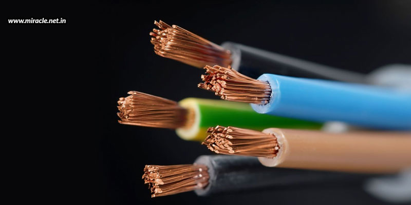
People generally use the terms wires and cables interchangeably, but in reality, both these terms are different. Wires are made of a single conductor, while cables are a group of conductors. Wires are bare and twisted, while cables have the wires running parallelly and twisted together to form a single case, with an outer insulation covering to protect it from abrasion, moisture, and wear and tear. The basic materials used to make such wires and cables are copper and aluminium.

Wire harness and cable assembly

These are two other terms that are often confused with each other, but there is a difference. Wire harnesses are a basic exterior coating, covering smaller wires within. The basic materials used to make a wire harness include thermoplastic and thermoset materials, which mildly protect the wires from certain weather conditions. Cables assemblies, on the other hand, are a group of cables wrapped in an outer layer, to keep the cables together and organized. These assemblies are made from heavy-duty materials like thermoplastic rubber, vinyl, or shrink-wrapped thermoplastic. Thus, cable assemblies serve a similar function to wire harnesses, being more durable so as to withstand tougher environments like heat, moisture, friction, etc.

Braided wires and coaxial cables

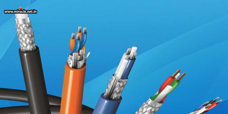
Basically, you’ll use solid stranded wires in your harness. But, if you want a stronger option, braided wires are a better choice. In a braided wire, many small strands of wire are formed into a braid; thus making it difficult to break or tear the wires easily. This is why critical industries like aerospace and mining use braided wires. Coaxial cables are also a type of braided wires, with an inner copper core, and a braided copper shield on top of the dielectric insulator, covered with another protective insulation or sheathing. These cables are ideal for transmission of audio, video, and radio frequencies, which is why they are often found in cable TV connections, home audio systems, DVD players, and the like.

Conductors

Conductors are wires made of copper, stainless steel, or copper alloys, responsible for carrying electrical signals. A wire has only one conductor, while a cable can have multiple conductors. It is the conductors that decide on the electrical properties of a wire or cable, such as operating temperature, solderability, weight, and corrosion resistance.

Connectors and terminals

Connectors and terminals join two circuits or wires, in a way that information and electric signals can pass. Connectors can complete an electric circuit by connecting two points, and terminals can form a connection between two conductors or wires. The most common types of connectors include power connectors, computer connectors, and audio connectors; the that of terminals include crimp terminals, turret terminals, and screw terminals.

Insulation

Insulation is the protective covering over a core or strands of wires or cables, which protects the wires and cables from external damage, breakage, and wear and tear.

With knowledge about the most basic terms associated with wires and cables, you should now be in a better position to understand as well as convey what you want. Even better, you can partner with a reliable and genuine cable assembly or wire harness manufacturer in India to help you. One such manufacturer is Miracle Electronics, where you can get only the best quality harnesses and assemblies that are made with the finest materials, and great craftsmanship, yet being delivered to you at the most reasonable prices!

Evaluating The Quality Of Control Transformers - Miracle Electronics

If you’ve gone through the multiple blogs that we’ve written about how transformers help transfer electrical power between two or more circuits effectively, you already know that transformers are highly effective in saving your projects from getting hampered, and helping production to take place without disturbance; thus becoming an integral part of our everyday lives . A control transformer is mainly created for purposes that demand electromagnetic and solenoid devices. Such transformers have an in-built capacitor that helps reduce variation in output and lets your machine do its work without any difficulties. But, this is possible when you have a good quality transformer that best fits your requirements.


How to evaluate the quality of a control transformer?

Winding material type – The two main materials used for winding are copper and aluminium. Copper is certainly the better choice as it is a better conductor, and also provides higher mechanical strength, while making the size of the transformers smaller. Aluminium windings are comparatively more affordable, but they are lower in conductive properties. Copper thus is certainly more efficient, but many applications choose aluminium because of their significant cost advantage. You must thus make your choice depending upon your individual application; and choose a transformer manufacturer who is apt at manufacturing both kinds of transformers so that he can work to fulfill your specific demands at any time.

Voltage and frequency – What Ampere or Wattage does your application load need? Considering this, you’ll be able to pick the best size and voltage rating device for your production. You need to determine the voltage and frequency of both the primary and secondary, in order to make a rational choice.

Life expectancy – The life of the insulation system is another important factor to consider. Insulation life is equivalent to the temperatures being experienced by insulation across the process. Hot spot temperatures are determined by adding the total of the winding angle, maximum ambient temperature, and standard winding temperature increase. Another factor you need to consider is the kVA rating that signifies the amount of kVA charging that occurs in the measured temperature increase. When used in standard operating conditions, including the allowed hot spot temperature with suitable insulation class, a standard life expectancy can be determined.

With the above aspects considered, you can guarantee the best fit control transformer for your application. After all, determining the best type of transformer that you need for your application is an important thing to do. More than that, you can approach a genuine transformer manufacturer in India, one like Miracle Electronics, who can provide you with only genuine high-quality products, and also advise you on the best kinds of transformers that can suit your requirements and applications. We specialize in manufacturing transformers of export quality that are acclaimed for unique features of excellent voltage regulation, durability, and compact design. You can get every kind of transformer here, like power, toroidal, medical isolation, audio, EI, UI, SMPS, and more. You can purchase from off-the-shelf products, or have your own transformers especially customized for your requirements .

Sunday, 27 December 2020

The Efficiency And Losses Of Transformers Explained - Miracle Electronics

We cannot neglect the importance of transformers , as we’ve become so dependent on every kind of electrical and electronic application, each of which requires a transformer to bring in safe amount of power for effective and safe performance. But, it is absolutely important that the transformers are efficient in their functioning so that any kinds of problems can be avoided. One important factor in transformer efficiency is “transfer loss”. Here’s all you need to know about transformer efficiency and transformer losses, so that you can get hold of the right kind of transformer.

What is transformer loss?

Transformer loss is the difference between output power and input power. There is no mechanical loss like friction or windage loss in an electrical transformer because it is a fixed device, but there are copper and iron losses present in a transformer. Also, there is the eddy current loss.

Copper loss/iron loss – In a transformer’s core, the process of magnetization reversal leads to hysteresis loss, which is dependent on the grade of iron, volume of iron, flux density value, and magnetic reversals frequency. The hysteresis loss or current loss of a transformer is dependent on the material’s magnetic property that is used for the construction of the core, which is why the losses are known as copper loss or iron loss. The windings in the transformer offer ohmic resistance, which also leads to copper loss. The copper loss for primary windings is I12R1, and for secondary windings is I22R2, where I1 and I2 are the currents flowing in the windings, and R1 and R2 are the resistances. Such copper loss is highly dependent on the load. 

Eddy current loss – The primary winding in a transformer is supplied with AC current, as a result of which magnetizing flux is set up, which in turn creates induced EMF in the secondary coil after coming in touch. However, some additional conducting parts like the iron body or steel core of a transformer also gets linked to the flux, which results in the circulation of small currents due to the induced EMF. This current is known as eddy current, which is responsible for energy dissipation in heat form.

What is transformer efficiency?

Transformer efficiency is important for economical functioning, which is determined by the ratio of output power to input power. A transformer can possess maximum efficiency when the iron and copper losses in it are equal.  You can get the most efficient transformers at Miracle Electronics, which is a reliable and recognized transformer manufacturer in India that offers transformers with maximum efficiency and minimal losses. This is possible as we have a team of skilled professionals using the latest technologies to be able to meet the highest quality standards and fulfill the demands of every kind of customer. You can buy all kinds of transformers here, such as power transformers, toroidal transformers, medical isolation transformers, three-phase transformers, EI transformers, UI transformers, SMPS transformers, and many more.


Tuesday, 22 December 2020

What Are Twin Axial High Speed IO Cables - Miracle Electronics

Copper twin axial raw wires have been developed for more than five decades now, and are yet being used in all kinds of diverse applications. Today, these wires, after receiving much trust and authority, are being used for several new generation I/O interface standard and custom wire assemblies. They are being used for both internal and external assembly applications within enterprise infrastructures, high performing computer systems, commercial data centers, and many other consumer applications.

However, these wires are yet quite expensive, which poses a challenge for manufacturers to produce budget-friendly ones, and for users to pay a little extra for the extra performance that they expect. But, in spite of the price, these wires are yet used preferably in expensive test equipment for 56 Gbps per lane circuits, and for handling 100W power closely adjacent to sensitive high-speed digital signaling per interface specifications like USB 3.1 and the latest power over Ethernet IEEE-802.3 specifications.

Here are some tips on how a wire assembly manufacturer can overcome these challenges, by considering these guidelines as part of the component engineering process. Although it is easy to cut down costs while designing a quality wire harness , but it could be a little challenging in the case of twin axial high speed I/O cables. 

  • Having relationships with strong suppliers can address any and all material, quality, process, performance, and testing variations details.
  • The raw wire from one reel should be used for I/O link assemblies because of slight, but critical performance variations from one reel to another. That’s because it depends on how tight the wire is reeled up, and the difficulty of maintaining structure symmetry. Generally, each reel of the raw wire is individually measured, characterized, and documented for use by the wire assembly supplier, and the traceability by the OEM or end user.
  • The wire conductor gauge size versus electrical signaling reach should be carefully considered. The dielectric material properties that will achieve needed signaling performance ranges must be looked out for. This may include evaluating solid, air, and foam types. Also, the process variation tolerance and control of bubble size, symmetry, density, and distribution must be looked at.
  • Pure copper conductor elements with very low oxygen content, when used, can optimize conductivity. The conductor silver-plating smoothness and purity must be considered, enabling best electrical skin effect relative to signal launch path, insertion loss, jitter, and reflection loss.
  • Twin axial differential pair elements need to be layered within the bundle for optimized element fan out and prepping, relative to the termination zone. The pair shields need to hold tight geometries when processing and wire termination prepping, and also for wire bundle shields and fillers. In addition, the bundle diameters and bend radius need to be designed relative to the wire routing.
  • Wire termination to contacts or PCB pads must be watchfully done for both signal and ground conductors and wire bundle shield termination. The best technologies must be used for every process right from wire termination shaping and smoothness to welding or soldering.

All in all, you need to find a manufacturer that is up to the mark and perfect at producing nothing but only the best for your application. And, Miracle Electronics is one such name that tops the list of the most reliable wire harness manufacturers from India, where you can get high performing wire harnesses, especially customized to your needs.


Monday, 14 December 2020

Flexible PCBs – The Advantages And Applications - Miracle Electronics

When you hear the word PCB, you immediately imagine a square or rectangular rigid green colour board with golden lines running haphazardly all over. We all are well-versed with such a depiction of the PCB, but how many of us are aware of a non-rigid/flexible printed circuit board!?


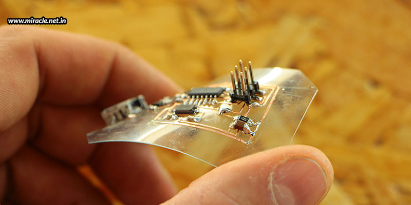
What is a flexible PCB, you may ask. Just as the name suggests, it is a PCB that is not rigid, but flexible in nature. The flexibility comes with the usage of a malleable base material, which holds the circuitry and components on top, just like a normal PCB. The materials used could be polyimide or polyester, with a very thin layer of copper over the board. But, this copper has a tendency to oxidize, which is why the copper layer is covered with another protective layer, such as solder, which has excellent electrical conductivity and zero corrosion capabilities. There are two types of soldering processes that can be followed – manual and laser. Manual soldering is one of the cheapest processes used for welding a PCB, while laser soldering is a faster method. Laser soldering uses the excitation of laser energy to transform into heat energy for soldering.

Advantages of flexible PCBs

Flexible PCBs are easy to install – With the market being filled with nanoelectronics, there is a very small space available to fit the PCBs.  Adjusting the PCB to set into such a compact space can be a challenge. Flexible PCBs male the task much easier.

Flexible PCBs reduce weight and volume – Because flexible PCBs are thin and light in weight, they can also reduce the volume and weight of electronic products, while offering flexibility of installation and excellent electrical properties.

Flexible PCBs offer low risks and high performance – Flexible PCBs reduce the interconnection required, which means lesser solder joints and contact creases. Due to this, potential failures are minimized and performance is improved.

Applications of flexible PCBs

Smartphones – The usage of flexible PCBs is highly increasing, especially in the smartphone industry. Flexible PCB manufacturers are contributing in the industry on a massive level! The demand of flexible PCBs has increased because of the demand of complex circuitries to be installed in the thinnest possible applications.

Wearables – Flexible PCBs have also found great demand in the industry of wearables. That’s because such smartwatches, fitness trackers, and every other kind of sensor-technology device needs to be worn on different parts of the body, which means flexibility is highly required to wrap body parts.

Heads-up displays – Another application is the Heads-up Display used in aerospace, which display operational data directly in the pilot’s field of vision, so that he can read critical operational data during flight, without having to look away from a potential target.

Hearing-assist devices – The medical industry also uses flexible PCBs in hearing-assist devices to provide higher range and resolution than traditional hearing devices, with the usage of flexible PCBs to help mount all the microphone, DSP, and battery in a tiny compact package that fits behind the ear.

To conclude, whenever you are looking for compact, thin, lightweight, flexible, reliable, and efficient PCBs, you know that you are looking for a flexible PCB assembly from India. Get in touch with Miracle Electronics and get your flexible PCBs designed and manufactured as per your requirements. Choose from single-layered, double-layered, and multi-layered options, and have your PCBs designed just the way you want them to be!


Tuesday, 1 December 2020

Building An Efficient PCB Layout - Miracle Electronics

 It is always wise to build PCB prototypes before the entire batch, no matter how big or small the volume of PCBs in a single lot. That’s because a PCB prototype will bring into focus how the PCB will exactly look like and how it will perform. Any faults detected in the prototype can be dealt with before manufacturing a complete batch, so as to avoid an entire lot of PCBs from being made useless, or requiring fixes.

But, the success of failure of a prototype highly depends upon how the PCB has been designed in the first place. Even before the prototyping phase, comes a phase where the designers design a PCB depending upon the requirements and configurations, and plan a layout, on which the engineers work to build a prototype. Any neglections or misinterpretations in the PCB layout can lead to wrongly built or erroneous PCB builds; which is something you certainly don’t want to encounter.

To be able to come up with an efficient PCB layout with no confusions or misunderstandings, there are certain points that need to be considered well; some of them being mentioned below.

Copper traces

It is the copper track that connects two points within the PCB. But, this conductive path can also have resistance. Generally, designers use the length, width, and thickness to control the resistance of the trace, and form the different levels of thickness of a PCB. But, it is always better to use a PCB trace width calculator to determine the optimal thickness for your project. Also, it should be kept in mind that traces on the external layers will cool off better and quicker, while heat from the internal layers are required to travel through the layers of copper, before being conducted. This is the reason why single layered PCBs are most preferred in simpler applications where they can be effectively used.

Distance between copper traces and fills

There must be enough room between the copper traces and fills to prevent any shock hazards. Solder marks aren’t always reliable conductors, which is why a good amount of distance between the two is judicious.

Distance between noise and analog traces

Placing both noise traces and analog traces together will certainly double the signals on the traces, which further leads to interference and short-circuiting. Thus, it is always wise to keep both these high frequency traces away from one another.

Placement of decoupling capacitors

Decoupling capacitors must be placed as near as possible to the power and ground pins of integrated circuits to increase efficiency. Capacitors placed farther away will have a reduced inductance ability.

Loop size

Loops within a PCB design should always be kept as small as possible. That’s because smaller loops have lower inductance and resistance. In addition, a PCB with high loops reduces the amount of high frequency voltage spikes.

With all these tips followed, one can come up with a reliable and efficient PCB layout. If you are in search of one such layout that can help you get the best possible PCB for your application, you can get in touch with Miracle Electronics, where you’ll not only get talented designers working to come up with the most efficient PCB layout, but also expert engineers to help you build a reliable PCB assembly from India. You can rely on Miracle Electronics for all kinds of high volume, medium sized, or even low volume projects, no matter what your industry and application.


Friday, 13 November 2020

How Are Copper Wire Cables Tested - Miracle Electronics

Copper wire cables are a very small part of any electronic application, but that doesn’t mean they are insignificant. In fact, they are one of the most important parts of a circuit that connects different parts and sends power or signals to them for an effective functioning. And, this is why it is highly crucial that these wires and cables are of the best quality. For this, one, you need reliable and experienced wire harness manufacturers from India, who make only genuine high-quality wires with no compromise; and two, you need thoroughly tested wire cables that ensure zero faults. Although a genuine manufacturer will himself test every product before delivering it to you, yet we put it up as a different point to bring to your notice the importance of testing.


Tests done by the manufacturer

There are a variety of different tests that are done on copper wire cables to ensure best quality and perfect functionality.

Continuity test – This test allows to check for solid wire connections within the cable. Multimeters are used to check this by measuring the current, voltage, and resistance of the circuit.

Resistance test – This test helps measure the voltage and current resistance within a cable, which can then be compared to the expected cable performance to reveal how well the cable is performing. An ohmmeter is used for this purpose, where it passes a small current through the cable and measures the voltage drop.

Isolation test – This test uses low voltage power to help see how well isolated the wires within the cable are. A megohmmeter is used to measure current leakage with a low voltage.

Shorts test – This test uses high voltage power to help find any shorts within the cable, which is not revealed when low voltage is used.

Miracle Electronics tops the list of wire harness manufacturers from India, who makes sure to conduct all the above tests and more to ensure high quality and high-performance wires and cables before delivering the same to clients.

Three tests after purchase

While your manufacturer should have done all the above-mentioned tests already, there are three other critical tests that should be done after the purchase. One is to be done during the installation, second during having it to perform the first time, and third is during frequent maintenance procedures.

During installation – You must check for any damage during transit, and ensure that the cables are working, upon installation.

When functioning first time – Once you install the cables, turn on your application and thoroughly check for any interference or problems. The cables must be compatible, and must seamlessly interact with the software and other elements involved with the application.

Frequent maintenance procedures – You must carry out maintenance procedures periodically to check if the integrity of the cables have been compromised after a set period of time, or following peak load times.

With all the above tests, you can ensure quality performance and safe procedures within the space where the application has been installed.


Wednesday, 21 October 2020

Cables And Wires For Medical Applications - Miracle Electronics

When looking to satisfy medical applications, you need a perfect manufacturer  that has a great experience of manufacturing cables and wires for such sensitive products. They must have a thorough understanding of the particularly rigorous standards and regulations that apply to the medical industry. After all, you’ll need only the highest quality cables and wires in the market, suitable for all kinds of medical applications like diagnostic equipment, laboratory equipment, treatment equipment, lighting systems, automation devices, and more.


Diagnostic equipment

Medical diagnostic equipment and imaging equipment like MRIs, PET scans, CT scans, X-rays, and ultrasounds are critical for the diagnosis and treatment of patient injuries and ailments. And, all such critical equipment requires high-performance and reliable wiring connections so that information can be transferred accurately and in a secured manner.

Laboratory equipment

Laboratory equipment like life support equipment, dialysis machines, ventilators, anesthetic dispensers, and more require cables that can ensure accurate measurement, monitoring, and analysis of patient health. These equipment are highly sensitive and critical, used to help medical professionals examine body fluids for signs of disease or infection.

Treatment equipment

There are a variety of tools that are used in the medical industry for treating a variety of health problems; for instance, surgical lasers, medical infusion pumps, and LASIK equipment, to name a few. All these equipment, as well as the operating tables must be equipped with reliable cables and wires to ensure appropriate positioning of the patient during sensitive procedures.

Lighting systems

When any kind of treatment is being executed, may it be a simple LASIK operation, or a significant heart operation, nothing can be executed successfully without the use of extremely bright lighting. And, for such bright lighting, it is important that extremely reliable and durable wires and cables are used that can withstand high power levels, and also extreme temperature fluctuations.

Automation devices

Automation is becoming more common in medical practice today to provide medical practitioners with accurate, quick, and efficient procedures. But, to be able to make the automation precise and reliable, data cables that receive and transmit instructions, and also sensor cables that transmit critical information to the operating system in real time, need to be efficient as well as have the ability to withstand all kinds of bends, turns, and other motions.

These are just some of the medical applications that use wires and cables of various types. There is so much more than the healthcare industry calls for. But, no matter what the application or requirement, every medical equipment and process requires efficient, high-performing, durable, and reliable connections. You thus need high quality cables and wires; and for that to be possible, you need experienced and trustworthy wire and cable manufacturers. Miracle Electronics is one of the best cable and wire harnessmanufacturers from India, where you can get not only all of the above, but also customized engineered solutions, tailored to meet your particular needs at the premises that is designed to create cable and wire products that meet the most stringent industry standards.


Friday, 16 October 2020

Copper Wires _ Benefits & Applications - Miracle Electronics

 Copper is a very common metal used in all kinds of electrical applications, because it is considered as one of the best materials for conducting electricity. Today, the material is used in electrical wiring for both domestic and industrial use in a variety of applications like electronic circuitry, home appliances, telecommunications, etc. In fact, half of all the copper that is mined today is used to produce wires and cable conductors! Copper is thus a versatile metal of the future.


What makes copper so popular and admired?

Copper possesses excellent electrical and thermal conductivity

Copper has the best know electrical and thermal conductivity, better than any other conducting metal. It has the least resistance to conduction, hence it can be used in even the highest conductivity applications like lightning rods for safety measures in buildings and skyscrapers.

Copper has great tensile strength

Copper has excellent tensile strength and can also resist a number of mechanical failures like stretching, breaking, necking, etc; thus achieving so much of admiration.

Copper is highly malleable and ductile

Copper is a very highly malleable and ductile metal, which makes it very easy to draw it into wires, strips, and strands. This is why copper finds so much admiration in the applications of wiring.

Copper can be easily soldered

Copper wires can be easily soldered to form connections, making connections easy for transmission and termination points. Moreover, the excellent strength that copper possesses makes it possible to pull it through different areas, and even tiny tight spaces to lay conduits.

Copper has good corrosion resistance

Copper’s great corrosion resistance makes it one of the best metals to be used for electrical transmission. Its low reactivity series does not let it corrode, thus making it an excellent choice to be used in wires.

Copper has excellent creep resistance

When a metal expands and contracts under certain cyclic load conditions, the deformation that results is known as creep. When there’s higher creep, a screw can deform a conductor and reduce contact pressure, which leads to resistance in joints, loose connections, oxidation, and overheating. But, copper has an almost negligible creep, making it the best metal to be used in a wire.

Types of copper wires

With the amazing properties that copper possesses, it now becomes clear why the metal is so popularly used in wires and cables. But, did you know that there are a variety of different copper wires available for you to choose from?

Solid copper wire – This is a single copper wire, bare or sheathed , in an insulating cover, used to transfer electricity.

Stranded copper wire – This is when numerous thin copper wires are wound together to form a single wire.

Copper cable – When copper wires are twisted, braided, twisted, or woven into a single assembly, a copper cable is produced.

We’ve learnt all about copper wires and cables, and how they are such a great choice. But, it is essential that you rely on a genuine copper wire manufacturer to ensure that you get good quality and unadulterated copper wires that are proven and certified. And, MiracleElectronics tops the list of the most reliable and trustworthy wire harness manufacturers from India, where you can get all kinds of wires and wire harness, customized to your specific needs, each being high on quality and certified for production processes.

Tuesday, 29 September 2020

Choosing Heavy Duty Connectors For Cable Assemblies - Miracle Electronics

 Designing cable assemblies for use in harsh environments poses a number of challenges, especially those that need to be used in industrial equipment that may be subjected to conditions like high temperatures, high humidity, water, chemicals, electromagnetic interference, vibration, impact, or particulate ingress from close proximity to moving factory components. Over time, exposure to such components starts to hamper conductivity, requiring repairs or replacements.

To avoid all such hassles and inconvenience, it is advisable that you choose to install heavy duty connectors for the cable assemblies that are to be used in applications that need to withstand one or more of the conditions and environments mentioned above. So, here’s a guide that can help you choose the best quality heavy duty connectors for your application.

The housing material

A die-cast aluminum housing should be the best choice as these are light weight yet highly impact resistant. However, if your application is to be used in wet environments, plastic connectors should be a better alternative as they won't rust or corrode. And, if your application is too small with tiny spaces, you can choose materials that provide EMI shielding instead.

The insert types

Heavy duty connectors with pluggable inserts that carry power, data, or signal to and from factory equipment have been traditionally used. But today, modular inserts that support an integrated hybrid cable assembly are more popularly used. Heavy duty connector systems need to meet the demands of the hybridization trend, which is why more and more customized cable assemblies are being preferred. And, with such customizations, modular connectors are more popularly used as they provide an integrated hybrid assembly that creates new considerations for power and signal wiring beyond the fundamentals of approval ratings, clamping type, and wire guage. The various insert types that you can choose from include fiber optic, pneumatic, D-sub, USB, M12, and RJ45.

The ratings and standards

IP ratings depict the level of protection that an electrical enclosure provides against solids and liquids, and NEMA ratings describe the environments where the enclosure can be used. You need to choose from such ratings, or buy standardized connectors to ensure their quality and performance.

The manufacturer

You need to choose the right cable assembly and connector manufacturer too; one that has experience, knowledge, skill, and expertise in the field. One such cable assembly manufacturer in India is Miracle Electronics, a contract manufacturer that is tooled for majority of industries such as electronics, aerospace, audio, and medical. You can have all kinds of cable assemblies manufactured here, some of them being EMI shielded assemblies, flat assemblies, ribbon assemblies, RF assemblies, airborne looms, military looms, and power cable assemblies. You can also have circular, D-sub, military specific, and many other kinds of connectors built here too. And, whatever kind of cables, assemblies, and connectors you have customized with Miracle Electronics, you can rest assured about the quality you’ll receive because every production process executed here is certified for quality to ISO 9001, AS9100C. Also, every product manufactured here is certified and approved by DGAQA and MSQAA for platform specific applications, after undergoing all kinds of tests for dimension, weight, continuity, Hi-Pot, Pull, and environment compliance.


Thursday, 10 September 2020

Why Should Industrial Bus Cables Be Standardized - Miracle Electronics

The two main sectors for series data cables are computer bus and industrial bus; the former being a communication system that transfers data between components inside or between computers; and the latter being a communication system that transfers data between components or devices at different levels in a manufacturing plant. But, it is the computer industry that has had greater success in achieving unbiased industry-wide standards, while the industrial sector is more independent, and can produce cables specifically for their brand names.

In the industrial world, there are a number of variations due to different speed and impedance requirements, ranging from 100 to 150 ohms. Moreover, manufacturers may design a hybrid cable for automotive manufacturing plants with components using PROFINET, INTERBUS, and Industrial Ethernet protocols, all in one cable; allowing them to connect their PLC logic to whatever control line happens to come on the next machine.

Protocol standardization

Industries are looking for open architecture interface as the need for plant-wide system compatibility increases. Ethernet protocol of 100 ohms seems to be a good choice in this case. Higher information speed requirements, diagnostic feedback of controls, and interest in motor feedback make Ethernet a great choice to offer the performance required. However, these requirements are still driven from the controls manufacturers’ system trademark, some of them being PROFINET, CC-Link IE, Industrial Ethernet, and Foundation Fieldbus HP. Yet, many independent special interest groups have started to come up and work for system compatibility of conventional Ethernet. One such example is Ethernet POWERLINK Standardization Group that has developed a formidable product offering with data transmission speeds of 100 Mbit/sec; and is waiting for component manufacturers to adopt their standard Ethernet protocol into their systems.

Connector standardization

The standardization of connectors is also being accepted as major device dealers are settling for metric-type connectors like M-8, M-10, and M-12. RJ45 is also used, but it is modified to provide larger gauge compatibility, harsh environment resistance, and shielding capabilities.

To conclude

As you can see, Ethernet-based architecture is becoming an accepted choice for serial bus networks, since the compatibility and standardization of Ethernet from the computer side, found in front office, drives the manufacturing side to generic products. However, the marketing side of the controls industry still continues to manufacture proprietary products, developing cable requirements that are exclusive to the brand. Having such a diversity of protocols allows cable manufacturers to offer a lot many different cable systems. Also, each architecture has a unique conductor configuration and electrical requirements.

From past to present

The goal of various bus protocols and designs developed over the last 50 years was to find a cable capable of fast computer speeds that could withstand electrical noise and harsh environments. To accomplish this goal, technology is advancing to produce fiber optic cables, which is more suited to these requirements.

Whatever kind of cables you’re looking for – basic or fiber optic – Miracle Electronics is where you should be. These are the most dependable and versatile wire harness manufacturers from India, manufacturing a variety of different types of cables and harnesses for a myriad of applications and industries. You can also get in touch to design the perfect customized cable harness for your requirements.


Monday, 7 September 2020

HDI PCBs _ Why And Where To Use Them - Miracle Electronics

As we’re all shifting more and more to studying, working, browsing, and shopping online, after the pandemic has struck us, our world is becoming even more dependent on digital technologies. Moreover, the digital world today is becoming even more complex; but the hardware associated with it is becoming smaller. For instance, PCBs are becoming smaller with more interconnections. This makes the applications they are used in sleek and lean. And, if they are portable, it becomes really convenient to carry the devices around.


The PCB industry plays a significant role in the development of all electronic gadgets that our lives revolve around today. And, to make it simpler and easier, PCB manufacturers are always coming up with newer trends; one such innovation being the HDI PCB, which is a smaller PCB assembly from India that is dense with high component count.

What is HDI PCB?

HDI PCBs are smaller PCBs with a high density component count, and thus more number of interconnections, but those that occupy lesser space. Although the components are placed very close to one another to reduce the size of the board, the functionality isn't compromised. The general HDI PCB is one that has an average of 120 to 160 pins per square inch, and a dense circuitry that is implemented through microvias, buried vias, and blind vias.

What are the advantages of HDI PCBs?

HDI PCBs offer many advantages over regular PCBs, some of them being a compact design, lighter weight, and great performance. In addition, the signal path length is reduced as the components are placed very close to one another, and the reflections of signal are reduced, which results in remarkably improved signal quality. Also, the implementation of stacked vias makes these boards a super shield against extreme environmental conditions. All in all, with so many advantages offered, HDI PCBs are extremely cost-effective.

What are the applications of HDI PCBs?

HDI PCBs, because of the benefits they offer, are used in a variety of industries, such as those listed below.

Smartphone industry – With smartphones becoming more of a necessity than a luxury, manufacturers are using HDI PCBs to make these phones even smaller, and thus, conveniently portable.

Automotive industry – Car manufacturers are using more of HDI PCBs to save significant space in the vehicles. Moreover, the integration of smaller and smarter electronic devices provides a better driving experience.

Medical industry – Medical devices manufactured today use more of HDI PCBs when they want to fit into small compact devices like implants, lab equipment, and imaging equipment. In diagnostic devices, miniaturized cameras using HDI PCBs can help get better and intricate picture quality.

Aerospace and military industries – Aerospace and military equipment like planes, missiles, and defense systems use HDI PCBs that can function better in extreme environments and hazardous conditions.

Wearable technology industry – Wearable devices like VR headsets, watches, and many others use HDI PCBs to make the devices sleek, while offering exceptional functionality.

You can see how HDI PCBs have revolutionized almost every industry today with usage in a variety of devices and applications. This has increased the demand for such PCBs. You may also opt for such advanced and improved PCBs to fit into your smaller and smarter products. You can choose from readily available PCBs or have your PCB assembly from India especially customized as per your requirements at Miracle Electronics, the leader in manufacturing a variety of PCB assemblies since more than a decade now.


Thursday, 6 August 2020

Switch Mode Power Supply Transformers _ What They Are - Miracle Electronics

 Switched mode power supply (SMPS) is an electronic power supply that incorporates a switching regulator to convert electrical power efficiently, by transferring power from a DC or AC source to DC loads. The pass transistor of an SMPS continually switches between low dissipation, full on, and full off states, spending very little time in the high dissipation transitions, which minimizes wasted energy. Also, by varying the ratio of on to off time, voltage regulation is achieved. This high power conversion efficiency with no energy wastage is an important advantage of an SMPS.

Unlike linear power supply transformers, SMPS are small and light due to the smaller size and weight of the transformers installed, which is why they are effectively used as replacements for linear regulators when high efficiency is required with lighter weight and smaller size. The transformers that are mainly composed of magnetic core and winding, are used for conversion, energy storage, and isolation. But, the materials used will affect the performance of the transformer, which will in turn affect the heat dissipation and working efficiency of the equipment. Thus, you need to be very sure about the materials that you are having installed in your SMPS transformer. This is why when planning on getting an SMPS transformer for your application, you need to approach only an expert transformer manufacturer in India, one like Miracle Electronics, who has immense knowledge about, and enough experience of manufacturing and working with SMPS transformers.

Advantages and disadvantages of using SMPS transformers

  • One of the main advantages of using SMPS transformers is that you can have efficiency up to 96% because the switching transistor dissipates very little power when acting like a switch. Other advantages include small size, light weight, and low noise. Also, the standby power loss is very low.
  • One disadvantage is that they are very complicated and they can cause electrical noise problems if not carefully suppressed; thus causing harmonic distortion.


Types of SMPS transformers

SMPS transformers are divided into two types – unipolar and bipolar. Unipolar transformers are characterized by a unipolar pulse as input voltage, and are divided into positive flyback voltage output. Bipolar transformers are characterized by a bipolar pulse as input voltage, with the output generally being bipolar pulse voltage. 

Materials used

As mentioned above, it is very important to choose the right materials for the SMPS transformer. There are three main components of an SMPS transformer – magnetic materials, wire materials, and bobbin materials.

Magnetic materials – These are soft ferrite which are divided into two categories according to their composition and application frequenct – MnZm and NiZn.

Wire materials – Polyurethane and polyester enameled wires are generally used to wind small electronic transformers, divided into thin paint and thick paint types, depending upon the thickness of the paint layer.

Bobbin materials – Bobbins of SMPS transformers are different from general transformers, as they play a dual role of mounting and positioning of the entire transformer, along with insulating and supporting the coil. Thus, the bobbin material needs to meet insulation requirements, as well as possess tensile strength and heat resistance.


Wednesday, 15 July 2020

Why Should You Opt For Core Cap Transformers - Miracle Electronics

The typical method of manufacturing a transformer involves creating a core, insulating it, winding a magnet wire around to create a primary winding, insulating it, winding a magnet wire over the insulation to create a secondary winding, and finally insulating it too, to complete the transformer.


What are core caps?

To support the primary and secondary windings, and to reduce leakage current, segmented core caps are used in alternate sectors. Several modular electrically insulating segments snap or join together to form core caps for covering the transformer core. These core cap modules insulate the windings from the core over the full range of windings, allowing double-wall insulation between adjacent windings, significantly reducing leakage current. They also help in direct cooling of the core by ambient or forced air, without interfering with the insulation. The segments of each module include a pair of spaced insulating walls between which a core-covering panel portion is connected. The walls are inclined at a predetermined angle to each other, typically 30, 45, or 60 degrees, which is what determines the number of segments required to complete one core cap.

Benefits of using core caps

Reduced time invested – With the installation of core caps, there is no need for ground and inter-winding insulation and outer wrap. Also, both the primary and secondary windings can be wound on one machine only. In addition, providing the core cap includes mounting holes, which means that the time to fill the center of the transformer with epoxy is not required. All of this results in lesser time invested to manufacture and handle the transformers.

Reduced weight of the transformer – As mentioned above, there is no epoxy required to fill the center of the transformers if core caps are installed. Besides, no mounting washer will also be necessary. Hence, the weight of the transformer is also considerably reduced.

Reduced costs – Assembling core caps requires lesser skill levels that other core insulation techniques. Also, the cost to tool a smaller part for injection moulding is lesser than the cost of tooling a larger part. Thus, the cost to tool and assemble the core caps is way lesser. This means that the overall manufacturing costs of the transformer will be lesser too.

Reduced temperature rise – With core caps, there is a direct path for heat to escape into the environment. There is also no inter-winding insulation and outer wrap that traps heat. Thus, with all windings having a direct path for heat to transfer to the environment, then the temperature rise of the transformer is also reduced.

As you can see, core cap transformers help with reducing the time, weight, and costs of the transformer to a considerable extent, while also reducing the heat buildup. So, it can be clearly seen why core cap transformers are much better than standard transformers. You now know which kind of transformers to opt for, for your next application.

No matter what industry you are working in, and what kind of transformers you need, Miracle Electronics is your one stop destination to design all your transformer requirements. You can get all kinds of bundles of massive energy from this power, toroidal, EI, UI, SMPS, audio, and medical transformer manufacturer in India. And, every transformer you receive will always be RoHS and REACH compliant, having you to worry less about its quality and performance.

Monday, 6 July 2020

Balanced Audio Cables Vs. Unbalanced Audio Cables - Miracle Electronics

When you buy an audio system, you expect it to work at an unmatched quality; and the quality of sound produced by a system is highly dependent on the kind of audio cables used. This is specifically important during a live event recording, or live streaming. If the right kinds of cables are not used, it will produce a lot of noise and distortion. It is thus very important that you know which cables you need to use. There are two typical kinds of cables that you can use – balanced and unbalanced. But, in order to know which one of the two cables you should be using for your application, you need to understand what these are where each one is applicable. So, let’s take a look.


What are unbalanced cables?

Unbalanced cables are those that consist of two wires inside a plastic casing – a ground wire and a signal wire. The signal wire lies in the center of the cable, passing the audio signal through. And, the ground wire surrounds the signal wire, shielding the main signal wire from external electronic interference coming from lights, televisions, radios, transformers, and other devices. The unbalanced cables take the audio signal from the equipment used, passing it to a mixer or another receiving device without any manipulation. This, although a simple process, makes the audio distorted and noisy. Unbalanced cables generally use two kinds of connectors – one is the standard tip sleeve ¼” connector, and the other is the FCA connector.

What are balanced cables?

Balanced cables are those that consist of three wires inside a plastic casing – one ground wire and two signal wires. While the ground wire performs the same function as in an unbalanced cable, the difference lies in the working of the signal wires. In balanced cables, the signal wires pass an identical audio signal through each wire. This results in balanced cables being used such that the equipment sending and receiving the signals each have a converter, which allows them to make use of both the signal wires. Sending two signals simultaneously results in putting them out of phase, this means that while the signals are identical, one of them is the inverted mirror opposite of the other. When such out-of-phase signals reach the receiving equipment, they are then put back in phase, reverting the mirrored signal back to its original form. Finally, the two matched signals are passed to the mixer. This results in any distortion produced going out of phase, canceling itself out, thus culminating into a much clearer audio without distortion. Balanced cables also use two kinds of connectors – tip ring sleeve connectors and XLR connectors.

Which cable is right for you?

After understanding the construction, working, and performance of balanced and unbalanced cables, you can conclude that balanced cables reduce the distortion in the audio, while unbalanced cables do not. Then, you would assume that one must always use balanced cables because of the better sound quality that they produce. But, you would be surprised to know that this is not always the case! Each cable has its own pros and cons, which is why you need to learn about the specific cable that can prove beneficial to you. So, here are some points to help.

The length of the cable – When you need to use cables that are long, probably more than 20 feet in length, unbalanced cables can pick up noise from any nearby audio system, bringing to you a distorted sound at the receiver’s end. Balanced cables do not pick up such surrounding noise; thus making them apt to be used for longer lengths.

The strength of the signal – The above point is again another proof that clearly says why you must use balanced cables for your system. But, hold on! You would like to know that balanced cables have a weaker signal than unbalanced cables. Yes, unbalanced cables have a very strong signal. Thus, it is better to use unbalanced cables to get an uninterrupted sound.

The price – Unbalanced cables are way cheaper than balanced cables – one because of their simple construction, and two because they aren’t distortion-free like balanced cables. Thus, unbalanced cables are generally 30-60% cheaper than their balanced counterparts. And, to add to that, even after you pay a good price for balanced cables, you will also need to invest in special balanced mixed equipment, which can add to your costs. So, you need to keep that in mind while planning to opt for balanced cables.

To sum up:

After reading all that is written above, we can simply come down to two points –

  • If you need cables that are to be within 10 feet of length, there should be no issue in buying unbalanced cables, because these cables when used at such short lengths can bring stronger signals, uninterrupted sound, and are less likely to pick up any surrounding hum. Thus, you can get good sound quality at a cheaper price.
  • If the cables you need to use are longer in length, and if you don’t mind investing a little extra for that amazing sound quality at the receiving end, then you must opt for a balanced cable. Then, you’ll get professional sound quality with no noise distortion, considering you are paying a good price!


So now, you are ready to make your choice . And, after taking up an informed decision, you can always buy a balanced power transformer to convert any unbalanced power to balanced power. For this, you can get highly efficient balanced studio power supply in India from Miracle Electronics, to bring an audible improvement in frequency response and stereo imaging.

Monday, 15 June 2020

Fiber Optic Cables _ The Types And Benefits - Miracle Electronics

The data transmission industry is in full swing with all sorts of data being transferred from one point to another for various applications to run. Cable assemblies are one important element of this industry, which are required to send a signal from one device to another. The copper wire within these assemblies is mainly responsible for transmitting data through electrical signals or pulses. But, with advancements in technology, this copper wire is being slowly replaced with fiber optic cables.
What are fiber optic cables?
Fiber optic cables use a completely different method to transmit data, as compared to copper wires. With these cables, the data is sent using light pulses that travel through the fibers of the cable, which are made up particularly of plastic or glass, so that light can penetrate them. The light signals transmitted are then shot through the cable, hitting the cable walls. Because light travels very fast, the fiber optic cables have a much higher speed than the traditional copper wire.
Types of fiber optic cables
There are various types of fiber optic cables available, the choice depending upon the end connector and application in which they are to be used. The three main types of fiber optic cables include single-mode fiber cables, multi-mode fiber cables, and plastic optical fiber cables. Let us look at each one of them in detail.
Single mode fiber cables These cables are those that have only one strand of glass fiber running through them, with a thickness ranging from 8.3 to 10 microns in diameter. These cables can transmit data in only one direction. In spite of this, these cables have a higher bandwidth, and thus cost more.
Multi mode fibers These cables have multiple strands of glass fibers running through them, with larger diameters that range from 50 to 100 microns. Because of the multiple strands within, these cables can follow a linear and a non-linear path. The thickness can bring to these cables a higher bandwidth, but restricts the length. Longer cables result in a distorted signal.
Plastic optical fiber cables As the name itself suggests, these cables have plastic fibers instead of glass fibers, making it a cheaper option for short-distance applications. However, plastic optic fibers can lose their signal over long distances.
Connectors used in fiber optic cables
The connectors used at the ends of the cable assemblies are equally important to make sure that the cable is secured and connected properly to the application. Let’s now also take a look at the various kinds of connectors used.
Fixed connectors – These connectors are fixed on an application via a screw and threaded end housing, serving the purpose of securing the cable assembly to the application with movement.
Lucent connectors – These connectors contain small ferrules and a push-pull latching mechanism, being most popularly used with single mode fibers. Subscriber connectors – These connectors have ceramic ferrules, and are used for push-pull applications with dual mode fibers.
Straight tip connectors – These connectors contain a unique design where a half-twist bayonet locking mechanism is used. They come equipped with a longer ferrule, primarily used with multi mode fiber assemblies.
Whatever your cable assembly requirements, you can get in touch with Miracle Electronics, the most versatile cable assembly manufacturer in India. Here, you’ll get all kinds of cable assemblies, along with a variety of connectors to suit your application.

Tuesday, 9 June 2020

Cable Faults - The Best Troubleshooting Tips - Miracle Electronics

How far can you go without electricity? Doesn’t seem like for more than a few minutes, does it? You can't live without your fans and air conditioners; and if your mobile battery is down, you can't stand the power cut-off for even a minute. It’s almost like you life is leaving you, now that you are so very dependent on your electronics, and have such less capacity to fight the heat. Imagine if you have to stay off electricity for hours together, or maybe an entire day!


This can easily happen in the case of a cable fault. If a cable fault is not identified, you won't be able to fix the problem, no matter how long it takes. It is thus important to understand a cable and its possible faults well. Locating the fault area can help fix the issue quicker, thus bringing your electricity, electrical appliances, and electronic appliances back to life. Understanding this, we have brought forward to you some of the best troubleshooting tips for cabling faults.

Visual inspection

Visual inspection can help identify any external damage. Any damaged cable should be replaced. If not, there could be problems in the connector, as this is where most of the issues originate from.

Damaged cable replacement

As soon as a faulty cable wire is detected, it is wise to throw it away. Install a new cord set in its place. One of the quickest ways is to route a new spare cable, or swap cables to make the machine get back to work faster.

In the case of multiple cables

If several cables are joined together, and the specific reason of the fault cannot be diagnosed, it is better to replace the entire cable system, so as to not waste time.

Connector issues

If the fault is one that is linked to the connector, it could be difficult to detect. This is when having an extra set of cables can be of great help.

Cable extenders

Cable extenders and repeaters are different technologies aimed at addressing longer USB cable runs. Improperly installed, inadequately powered, defective extenders can cause significant problems. A signal delay may mean problem in the cable extenders. You must thus use multiple active USB repeaters or a single active USB extender. At the same time, avoid cascading multiple active USB extenders.

Other issues

Other issues that may not be with the cable could mean issues with the wall plates or adapters. Wall plates may bring the possibility of poor or loose connections; so you need to check all the front and back of the wall plate to ensure that they are screwed in well. Adapters may also be an issue if the right ones are not selected. There are a variety of formats and sizes of adapters available. If the wrong one is used, it may result in jostling or snapping off of the adapters.

As we can see, cables are one of the most challenging elements of any system. Using cables for your application other than those supplied by the manufacturer can ass yet another level of complexity. This is why it is always suggested that you have your cables particularly customized for your precise application by an experienced and expert cable assembly manufacturer in India, one like Miracle Electronics. Using such specifically designed cables and assemblies from reputed manufacturers will have your cables last longer, and your applications function better for longer too.