Wednesday 30 December 2020

Basic Terms You Need To Know About A Wire Harness - Miracle Electronics

Looking to order a custom wire harness? That’s a very wise decision, because a customized wire harness is certainly a better choice that a standard available one. But, if you think customizing is an easy task, hold on. Until and unless you consider certain aspects, you won’t be able to make the right decision. Certain terms, in the field of wire harnesses, are used interchangeably by a layman, but essentially, every term is different, and you must be able to understand what you want exactly, and what that particular feature is known as, so that you can convey the same to the manufacturer and get what you precisely want.

Wires and cables

People generally use the terms wires and cables interchangeably, but in reality, both these terms are different. Wires are made of a single conductor, while cables are a group of conductors. Wires are bare and twisted, while cables have the wires running parallelly and twisted together to form a single case, with an outer insulation covering to protect it from abrasion, moisture, and wear and tear. The basic materials used to make such wires and cables are copper and aluminium.

Wire harness and cable assembly

These are two other terms that are often confused with each other, but there is a difference. Wire harnesses are a basic exterior coating, covering smaller wires within. The basic materials used to make a wire harness include thermoplastic and thermoset materials, which mildly protect the wires from certain weather conditions. Cables assemblies, on the other hand, are a group of cables wrapped in an outer layer, to keep the cables together and organized. These assemblies are made from heavy-duty materials like thermoplastic rubber, vinyl, or shrink-wrapped thermoplastic. Thus, cable assemblies serve a similar function to wire harnesses, being more durable so as to withstand tougher environments like heat, moisture, friction, etc.

Braided wires and coaxial cables

Basically, you’ll use solid stranded wires in your harness. But, if you want a stronger option, braided wires are a better choice. In a braided wire, many small strands of wire are formed into a braid; thus making it difficult to break or tear the wires easily. This is why critical industries like aerospace and mining use braided wires. Coaxial cables are also a type of braided wires, with an inner copper core, and a braided copper shield on top of the dielectric insulator, covered with another protective insulation or sheathing. These cables are ideal for transmission of audio, video, and radio frequencies, which is why they are often found in cable TV connections, home audio systems, DVD players, and the like.

Conductors

Conductors are wires made of copper, stainless steel, or copper alloys, responsible for carrying electrical signals. A wire has only one conductor, while a cable can have multiple conductors. It is the conductors that decide on the electrical properties of a wire or cable, such as operating temperature, solderability, weight, and corrosion resistance.

Connectors and terminals

Connectors and terminals join two circuits or wires, in a way that information and electric signals can pass. Connectors can complete an electric circuit by connecting two points, and terminals can form a connection between two conductors or wires. The most common types of connectors include power connectors, computer connectors, and audio connectors; the that of terminals include crimp terminals, turret terminals, and screw terminals.

Insulation

Insulation is the protective covering over a core or strands of wires or cables, which protects the wires and cables from external damage, breakage, and wear and tear.

With knowledge about the most basic terms associated with wires and cables, you should now be in a better position to understand as well as convey what you want. Even better, you can partner with a reliable and genuine cable assembly or wire harness manufacturer in India to help you. One such manufacturer is Miracle Electronics, where you can get only the best quality harnesses and assemblies that are made with the finest materials, and great craftsmanship, yet being delivered to you at the most reasonable prices!

Evaluating The Quality Of Control Transformers - Miracle Electronics

If you’ve gone through the multiple blogs that we’ve written about how transformers help transfer electrical power between two or more circuits effectively, you already know that transformers are highly effective in saving your projects from getting hampered, and helping production to take place without disturbance; thus becoming an integral part of our everyday lives . A control transformer is mainly created for purposes that demand electromagnetic and solenoid devices. Such transformers have an in-built capacitor that helps reduce variation in output and lets your machine do its work without any difficulties. But, this is possible when you have a good quality transformer that best fits your requirements.


How to evaluate the quality of a control transformer?

Winding material type – The two main materials used for winding are copper and aluminium. Copper is certainly the better choice as it is a better conductor, and also provides higher mechanical strength, while making the size of the transformers smaller. Aluminium windings are comparatively more affordable, but they are lower in conductive properties. Copper thus is certainly more efficient, but many applications choose aluminium because of their significant cost advantage. You must thus make your choice depending upon your individual application; and choose a transformer manufacturer who is apt at manufacturing both kinds of transformers so that he can work to fulfill your specific demands at any time.

Voltage and frequency – What Ampere or Wattage does your application load need? Considering this, you’ll be able to pick the best size and voltage rating device for your production. You need to determine the voltage and frequency of both the primary and secondary, in order to make a rational choice.

Life expectancy – The life of the insulation system is another important factor to consider. Insulation life is equivalent to the temperatures being experienced by insulation across the process. Hot spot temperatures are determined by adding the total of the winding angle, maximum ambient temperature, and standard winding temperature increase. Another factor you need to consider is the kVA rating that signifies the amount of kVA charging that occurs in the measured temperature increase. When used in standard operating conditions, including the allowed hot spot temperature with suitable insulation class, a standard life expectancy can be determined.

With the above aspects considered, you can guarantee the best fit control transformer for your application. After all, determining the best type of transformer that you need for your application is an important thing to do. More than that, you can approach a genuine transformer manufacturer in India, one like Miracle Electronics, who can provide you with only genuine high-quality products, and also advise you on the best kinds of transformers that can suit your requirements and applications. We specialize in manufacturing transformers of export quality that are acclaimed for unique features of excellent voltage regulation, durability, and compact design. You can get every kind of transformer here, like power, toroidal, medical isolation, audio, EI, UI, SMPS, and more. You can purchase from off-the-shelf products, or have your own transformers especially customized for your requirements .

Sunday 27 December 2020

The Efficiency And Losses Of Transformers Explained - Miracle Electronics

We cannot neglect the importance of transformers , as we’ve become so dependent on every kind of electrical and electronic application, each of which requires a transformer to bring in safe amount of power for effective and safe performance. But, it is absolutely important that the transformers are efficient in their functioning so that any kinds of problems can be avoided. One important factor in transformer efficiency is “transfer loss”. Here’s all you need to know about transformer efficiency and transformer losses, so that you can get hold of the right kind of transformer.

What is transformer loss?

Transformer loss is the difference between output power and input power. There is no mechanical loss like friction or windage loss in an electrical transformer because it is a fixed device, but there are copper and iron losses present in a transformer. Also, there is the eddy current loss.

Copper loss/iron loss – In a transformer’s core, the process of magnetization reversal leads to hysteresis loss, which is dependent on the grade of iron, volume of iron, flux density value, and magnetic reversals frequency. The hysteresis loss or current loss of a transformer is dependent on the material’s magnetic property that is used for the construction of the core, which is why the losses are known as copper loss or iron loss. The windings in the transformer offer ohmic resistance, which also leads to copper loss. The copper loss for primary windings is I12R1, and for secondary windings is I22R2, where I1 and I2 are the currents flowing in the windings, and R1 and R2 are the resistances. Such copper loss is highly dependent on the load. 

Eddy current loss – The primary winding in a transformer is supplied with AC current, as a result of which magnetizing flux is set up, which in turn creates induced EMF in the secondary coil after coming in touch. However, some additional conducting parts like the iron body or steel core of a transformer also gets linked to the flux, which results in the circulation of small currents due to the induced EMF. This current is known as eddy current, which is responsible for energy dissipation in heat form.

What is transformer efficiency?

Transformer efficiency is important for economical functioning, which is determined by the ratio of output power to input power. A transformer can possess maximum efficiency when the iron and copper losses in it are equal.  You can get the most efficient transformers at Miracle Electronics, which is a reliable and recognized transformer manufacturer in India that offers transformers with maximum efficiency and minimal losses. This is possible as we have a team of skilled professionals using the latest technologies to be able to meet the highest quality standards and fulfill the demands of every kind of customer. You can buy all kinds of transformers here, such as power transformers, toroidal transformers, medical isolation transformers, three-phase transformers, EI transformers, UI transformers, SMPS transformers, and many more.


Tuesday 22 December 2020

What Are Twin Axial High Speed IO Cables - Miracle Electronics

Copper twin axial raw wires have been developed for more than five decades now, and are yet being used in all kinds of diverse applications. Today, these wires, after receiving much trust and authority, are being used for several new generation I/O interface standard and custom wire assemblies. They are being used for both internal and external assembly applications within enterprise infrastructures, high performing computer systems, commercial data centers, and many other consumer applications.

However, these wires are yet quite expensive, which poses a challenge for manufacturers to produce budget-friendly ones, and for users to pay a little extra for the extra performance that they expect. But, in spite of the price, these wires are yet used preferably in expensive test equipment for 56 Gbps per lane circuits, and for handling 100W power closely adjacent to sensitive high-speed digital signaling per interface specifications like USB 3.1 and the latest power over Ethernet IEEE-802.3 specifications.

Here are some tips on how a wire assembly manufacturer can overcome these challenges, by considering these guidelines as part of the component engineering process. Although it is easy to cut down costs while designing a quality wire harness , but it could be a little challenging in the case of twin axial high speed I/O cables. 

  • Having relationships with strong suppliers can address any and all material, quality, process, performance, and testing variations details.
  • The raw wire from one reel should be used for I/O link assemblies because of slight, but critical performance variations from one reel to another. That’s because it depends on how tight the wire is reeled up, and the difficulty of maintaining structure symmetry. Generally, each reel of the raw wire is individually measured, characterized, and documented for use by the wire assembly supplier, and the traceability by the OEM or end user.
  • The wire conductor gauge size versus electrical signaling reach should be carefully considered. The dielectric material properties that will achieve needed signaling performance ranges must be looked out for. This may include evaluating solid, air, and foam types. Also, the process variation tolerance and control of bubble size, symmetry, density, and distribution must be looked at.
  • Pure copper conductor elements with very low oxygen content, when used, can optimize conductivity. The conductor silver-plating smoothness and purity must be considered, enabling best electrical skin effect relative to signal launch path, insertion loss, jitter, and reflection loss.
  • Twin axial differential pair elements need to be layered within the bundle for optimized element fan out and prepping, relative to the termination zone. The pair shields need to hold tight geometries when processing and wire termination prepping, and also for wire bundle shields and fillers. In addition, the bundle diameters and bend radius need to be designed relative to the wire routing.
  • Wire termination to contacts or PCB pads must be watchfully done for both signal and ground conductors and wire bundle shield termination. The best technologies must be used for every process right from wire termination shaping and smoothness to welding or soldering.

All in all, you need to find a manufacturer that is up to the mark and perfect at producing nothing but only the best for your application. And, Miracle Electronics is one such name that tops the list of the most reliable wire harness manufacturers from India, where you can get high performing wire harnesses, especially customized to your needs.


Monday 14 December 2020

Flexible PCBs – The Advantages And Applications - Miracle Electronics

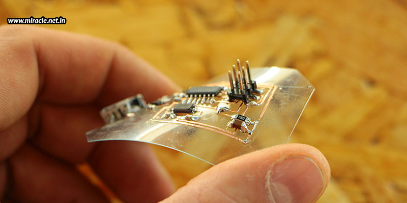
When you hear the word PCB, you immediately imagine a square or rectangular rigid green colour board with golden lines running haphazardly all over. We all are well-versed with such a depiction of the PCB, but how many of us are aware of a non-rigid/flexible printed circuit board!?


What is a flexible PCB, you may ask. Just as the name suggests, it is a PCB that is not rigid, but flexible in nature. The flexibility comes with the usage of a malleable base material, which holds the circuitry and components on top, just like a normal PCB. The materials used could be polyimide or polyester, with a very thin layer of copper over the board. But, this copper has a tendency to oxidize, which is why the copper layer is covered with another protective layer, such as solder, which has excellent electrical conductivity and zero corrosion capabilities. There are two types of soldering processes that can be followed – manual and laser. Manual soldering is one of the cheapest processes used for welding a PCB, while laser soldering is a faster method. Laser soldering uses the excitation of laser energy to transform into heat energy for soldering.

Advantages of flexible PCBs

Flexible PCBs are easy to install – With the market being filled with nanoelectronics, there is a very small space available to fit the PCBs.  Adjusting the PCB to set into such a compact space can be a challenge. Flexible PCBs male the task much easier.

Flexible PCBs reduce weight and volume – Because flexible PCBs are thin and light in weight, they can also reduce the volume and weight of electronic products, while offering flexibility of installation and excellent electrical properties.

Flexible PCBs offer low risks and high performance – Flexible PCBs reduce the interconnection required, which means lesser solder joints and contact creases. Due to this, potential failures are minimized and performance is improved.

Applications of flexible PCBs

Smartphones – The usage of flexible PCBs is highly increasing, especially in the smartphone industry. Flexible PCB manufacturers are contributing in the industry on a massive level! The demand of flexible PCBs has increased because of the demand of complex circuitries to be installed in the thinnest possible applications.

Wearables – Flexible PCBs have also found great demand in the industry of wearables. That’s because such smartwatches, fitness trackers, and every other kind of sensor-technology device needs to be worn on different parts of the body, which means flexibility is highly required to wrap body parts.

Heads-up displays – Another application is the Heads-up Display used in aerospace, which display operational data directly in the pilot’s field of vision, so that he can read critical operational data during flight, without having to look away from a potential target.

Hearing-assist devices – The medical industry also uses flexible PCBs in hearing-assist devices to provide higher range and resolution than traditional hearing devices, with the usage of flexible PCBs to help mount all the microphone, DSP, and battery in a tiny compact package that fits behind the ear.

To conclude, whenever you are looking for compact, thin, lightweight, flexible, reliable, and efficient PCBs, you know that you are looking for a flexible PCB assembly from India. Get in touch with Miracle Electronics and get your flexible PCBs designed and manufactured as per your requirements. Choose from single-layered, double-layered, and multi-layered options, and have your PCBs designed just the way you want them to be!


Tuesday 1 December 2020

Building An Efficient PCB Layout - Miracle Electronics

 It is always wise to build PCB prototypes before the entire batch, no matter how big or small the volume of PCBs in a single lot. That’s because a PCB prototype will bring into focus how the PCB will exactly look like and how it will perform. Any faults detected in the prototype can be dealt with before manufacturing a complete batch, so as to avoid an entire lot of PCBs from being made useless, or requiring fixes.

But, the success of failure of a prototype highly depends upon how the PCB has been designed in the first place. Even before the prototyping phase, comes a phase where the designers design a PCB depending upon the requirements and configurations, and plan a layout, on which the engineers work to build a prototype. Any neglections or misinterpretations in the PCB layout can lead to wrongly built or erroneous PCB builds; which is something you certainly don’t want to encounter.

To be able to come up with an efficient PCB layout with no confusions or misunderstandings, there are certain points that need to be considered well; some of them being mentioned below.

Copper traces

It is the copper track that connects two points within the PCB. But, this conductive path can also have resistance. Generally, designers use the length, width, and thickness to control the resistance of the trace, and form the different levels of thickness of a PCB. But, it is always better to use a PCB trace width calculator to determine the optimal thickness for your project. Also, it should be kept in mind that traces on the external layers will cool off better and quicker, while heat from the internal layers are required to travel through the layers of copper, before being conducted. This is the reason why single layered PCBs are most preferred in simpler applications where they can be effectively used.

Distance between copper traces and fills

There must be enough room between the copper traces and fills to prevent any shock hazards. Solder marks aren’t always reliable conductors, which is why a good amount of distance between the two is judicious.

Distance between noise and analog traces

Placing both noise traces and analog traces together will certainly double the signals on the traces, which further leads to interference and short-circuiting. Thus, it is always wise to keep both these high frequency traces away from one another.

Placement of decoupling capacitors

Decoupling capacitors must be placed as near as possible to the power and ground pins of integrated circuits to increase efficiency. Capacitors placed farther away will have a reduced inductance ability.

Loop size

Loops within a PCB design should always be kept as small as possible. That’s because smaller loops have lower inductance and resistance. In addition, a PCB with high loops reduces the amount of high frequency voltage spikes.

With all these tips followed, one can come up with a reliable and efficient PCB layout. If you are in search of one such layout that can help you get the best possible PCB for your application, you can get in touch with Miracle Electronics, where you’ll not only get talented designers working to come up with the most efficient PCB layout, but also expert engineers to help you build a reliable PCB assembly from India. You can rely on Miracle Electronics for all kinds of high volume, medium sized, or even low volume projects, no matter what your industry and application.